
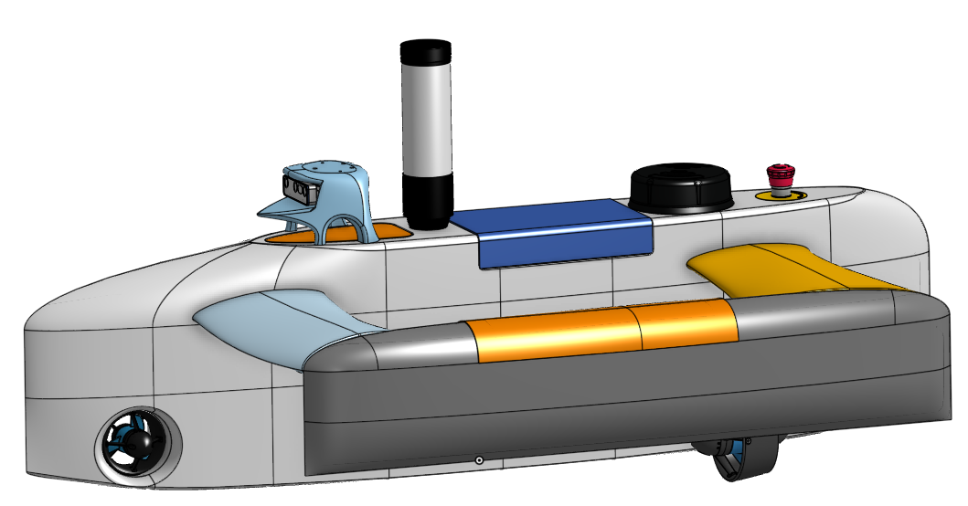
This project was meant to fill a gap in the availability of easy-to-understand resources related to hull design. I first identified this gap when attempting to design the first hull used by SeaBotics. With Ali as a mentor, I worked to find an overall process that functioned well for designing future hulls, both for myself and for upcoming students in SeaBotics.
Since this work was conducted in conjunction with SeaBotics, the process focuses on smaller surface drone hulls. Consequently, the requirements of larger vessels, such as engine rooms and related space constraints, were not taken into account.
The work consisted of reviewing books and articles on hull design, consulting with ship designers, and refining the approach through trial and error.
Regarding literature, Principles of Naval Architecture was recommended to me and widely considered online as the standard reference to follow. Volume II was the most relevant for this project, as it covers resistance. Key findings indicate that a hull symmetric from bow to stern performs best, especially when the geometry transitions smoothly. Additionally, evaluating how the hull or hulls generate waves is essential.
Building on this, a ship designer in the US (Datawave Marine Solutions) recommended looking into a program called Michlet and its expansion, Godzilla. Michlet calculates the water and wave resistance of a hull defined by input parameters. Godzilla extends this capability by allowing the user to specify parameter ranges, iteratively searching for optimal geometry and hull placements for hydrodynamic performance. The resulting hull shapes are output as point matrix files.
The process then involved transferring these points into CAD software (Onshape), which required several custom FeatureScripts. A challenge encountered during this phase was that CAD tools do not automatically interpolate space between points accurately, requiring manual guidance to avoid suboptimal surfaces. Increasing the point density and station count proved too computationally intensive in Godzilla, as the parameter search had already saturated after over 300,000 iterations.
The current workaround involves creating Bézier curves that align with the generated points. While functional, this method is not optimal as it demands significant manual effort and reduces the point cloud to a reference guide. To address this limitation, future work could focus on developing an alternative to Michlet/Godzilla that exports geometry better suited for CAD, such as NURBS surfaces, or integrates directly with the Onshape API.
Design validation is another critical step. Following recommendations from DMS, component fitting should be verified before CAD modeling progresses too far. If issues arise, earlier stages must be revisited, alongside performance evaluations of the hull in water.
Evaluating hydrodynamic performance is achievable using CFD. SeaBotics utilizes Star-CCM+; however, fully mastering Star-CCM+ was outside the scope of this project due to time constraints. This represents a promising direction for future work. Essential tests include static water performance (to determine waterline and internal stability), straight-line motion (to assess squatting behavior), and turning performance (to evaluate interaction between components and multi-hull configurations).
Learning has definitely been a great part of the project, not only am I, as a student and designer, now more capable in my designs for hulls. I am also, as the leader for mechanical design, now that this procedure worked out, better prepared to guide those starting out with design in SeaBotics.
The work in SeaBotics and here has shown me, Fabian, the way I want to take my career as an engineer. Design for hulls and vessels, and also mechanical design with simulation work, is what I now intend to pursue. This project has therefore been an integral part of my path forward.
The full procedure can be found at:
https://docs.google.com/document/d/1-rDOrtyeN3T7Oli0Itw5WWQupiwj223YNxL9LZ7m_pQ/edit?usp=sharing